
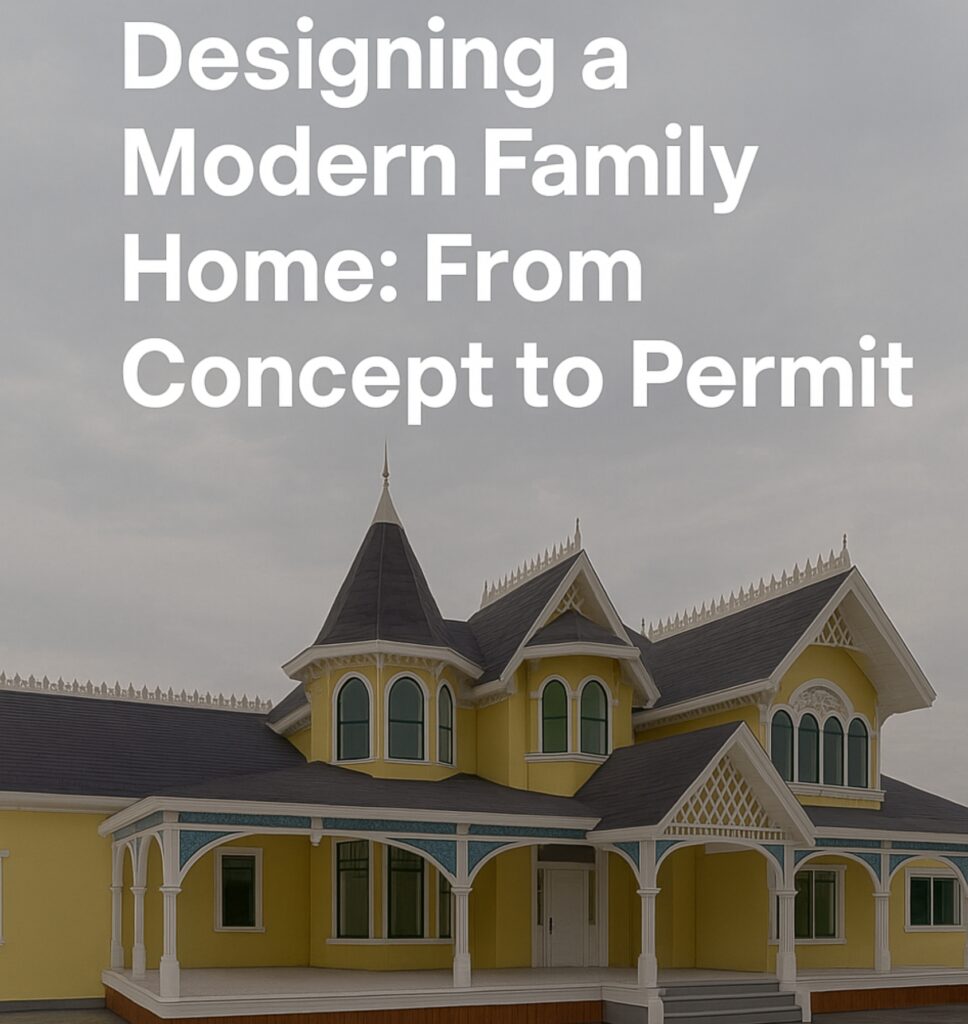
Residential Permit Architecture: From Concept to Permit in a Day
Project Snapshot: A Full Permit Set
At Unified Studio Architect, we specialize in transforming early-stage residential ideas into actionable, code-compliant permit documents—fast. In this project, a client submitted a basic hand-drawn layout for a single-family home and needed a full architectural set for permit submission and construction coordination.
Using our agile residential permit architecture process, we converted the rough concept into a comprehensive drawing set covering structure, spatial design, utilities, and visualization—all within one working day.
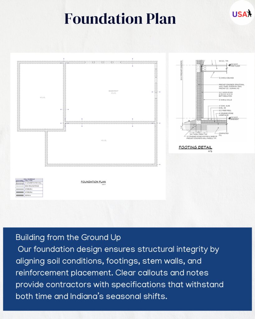
Foundation Plan: Building a Structurally Sound Base
We began with the foundation—the literal and technical groundwork of the home:
Footing Details: Continuous and isolated footings for load-bearing walls and columns were defined with dimensions and rebar callouts.
Stem Walls: Shown with height, thickness, and intersecting slab edges.
Slab Integration: Expansion joints, slab thickness, and vapor barriers noted per region-specific construction standards.
Code Notes: Regional frost depth, anchor bolt spacing, and minimum compressive strength for concrete were annotated.
This sheet became the reference point for engineering teams and inspections.
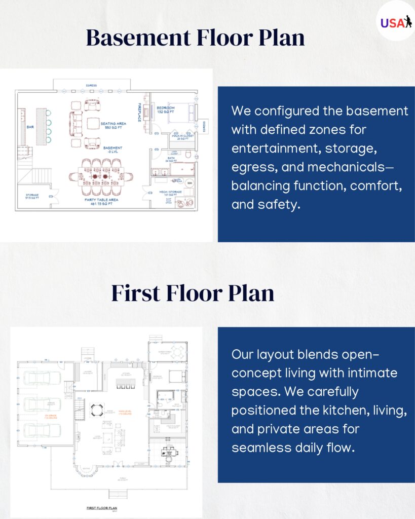
Basement and First Floor Design: Optimizing for Daily Living
The floor plans were shaped not only for code but for livability and space utilization.
Basement Plan
Mechanical room, storage, and entertainment zones were laid out to reduce HVAC and plumbing crossovers.
Clearances for stair headroom, egress windows, and future finish options were documented.
Strategic placement of columns ensured minimum visual obstructions and optimal support.
First Floor Plan
A semi-open layout balanced family gathering zones with private bedroom clusters.
Circulation paths were modeled to support natural light and minimize wasted corridors.
Kitchen, pantry, and mudroom proximity improved flow between indoor and outdoor access points.
All room dimensions were to scale, and load transfer paths were reconciled with the structural plan.
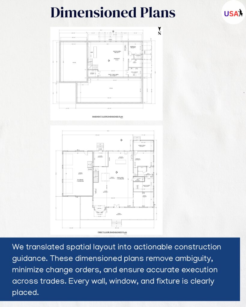
Dimensioned Floor Plan: Clarity for Construction Crews
A dedicated sheet focused on precise construction callouts:
Room Sizes and Wall Runs: Every partition had to-the-inch dimensions.
Opening Sizes: Windows and doors were dimensioned from rough opening to centerline.
Stair Details: Riser height, tread depth, and landing clearances included.
Material Tags: Wall types, slab edges, and framing notes were called out for early procurement.
Builders and contractors rely on this plan to begin on-site layout work without errors.
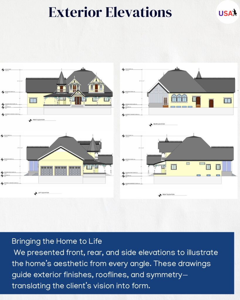
Exterior Elevations: Visual and Structural Cues
To illustrate exterior form and coordinate finishes, we delivered four elevations:
Roof Pitch and Overhangs: Accurately drawn with eave depth, gable termination, and ridge height.
Siding and Finish Layers: Callouts for horizontal lap siding, window trims, and base detailing.
Opening Heights: Aligned with floor levels for unified exterior proportions.
Chimney and Gable Features: Enhanced curb appeal and architectural balance.
These elevations help homeowners envision the final result and assist city reviewers with form compliance.
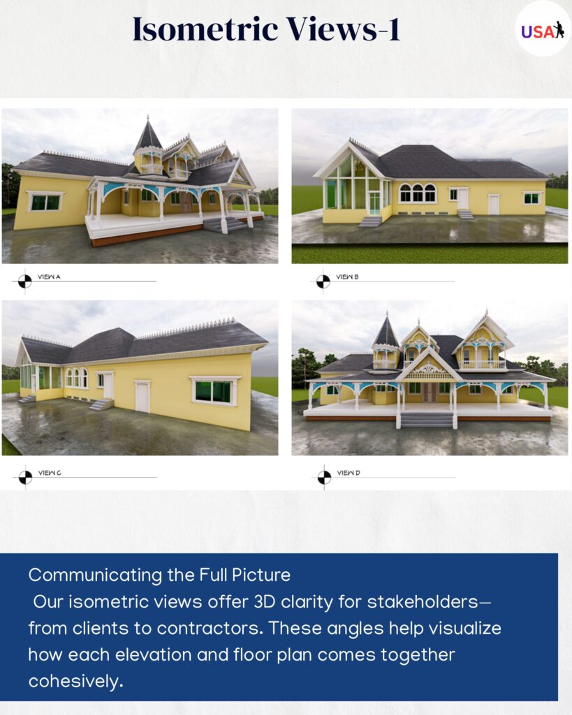
Exterior Elevations: Visual and Structural Cues
To support design visualization:
Multiple 3D isometric views were generated showing overall massing and form articulation.
Cutaways displayed spatial relationships across floors.
Front perspectives helped communicate the façade design to HOAs and stakeholders.
These views are particularly valuable when projects enter the presentation or marketing phase.
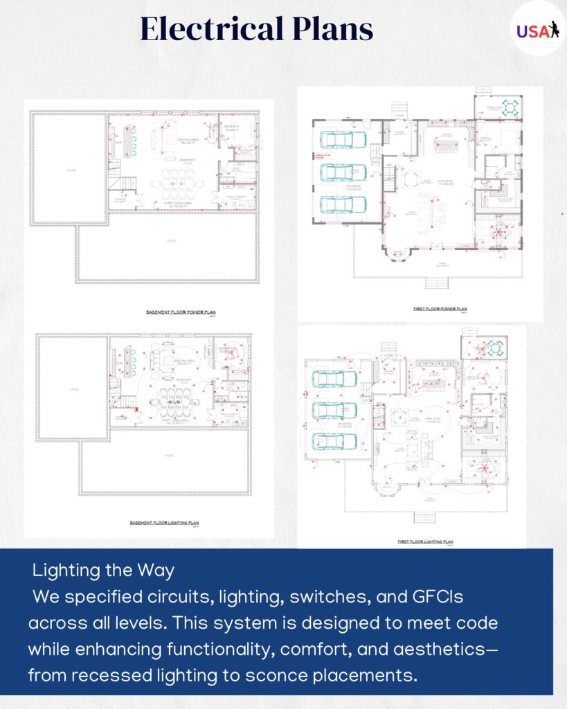
Electrical Layout: Designed for Real-World Functionality
The electrical plan considered both building code and daily use:
Lighting Strategy: Ambient, task, and accent lighting placements per room function.
Switch Control Paths: Logical switch locations and multi-way switching for convenience.
Dedicated Circuits: For kitchen appliances, HVAC equipment, and laundry systems.
NEC Compliance: All outlets, arc fault protections, and GFCI placements conformed to the latest National Electrical Code.
This sheet gives electricians clear guidelines while reducing back-and-forth during rough-ins.
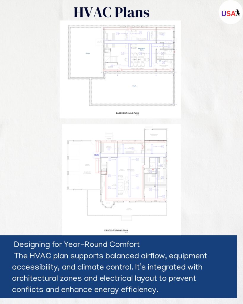
HVAC Plan: Comfort Engineered for Efficiency
Our mechanical layout combined system performance with construction practicality:
Duct Routing: Main trunk and branch ducts were positioned to avoid beams, framing clashes, and soffits.
Equipment Sizing and Zoning: Furnace, condenser, and air handler placements scaled to service area.
Return Air and Fresh Ventilation: Strategically placed for circulation and indoor air quality.
Code Checks: Met energy efficiency requirements and clearance codes.
The HVAC layout formed the backbone of the home’s comfort system, supporting future energy audits and upgrades.
Coordinated, Code-Compliant Permit Package
By the end of the day, Unified Studio Architect delivered:
A full residential permit architecture drawing set
Sheets for structural, spatial, mechanical, and electrical coordination
Aesthetic clarity for client and community review
All documentation aligned with local building code, energy standards, and inspection guidelines
Outcome: Approval-Ready Architecture in Record Time
With decades of combined permit experience and a streamlined documentation system, Unified Studio Architect brings unmatched speed and accuracy to residential design.
What started as a napkin sketch became a full permit submission in a single day—ready for city review, contractor pricing, and seamless construction.
Need permit drawings on a tight timeline? Our residential permit architecture process delivers precision, compliance, and confidence—fast.